In this tutorial, I will describe the step of creating a Hello world UART monitoring & I/O control application.
This article is a continuing tutorial from FPGA Tutorial (Hello world UART monitoring & I/O control) (Part 1 Vivado)
Step 9 Create a new Hello World Application Project
After set workspace directory from previous step Vitis program will launch new window as below.

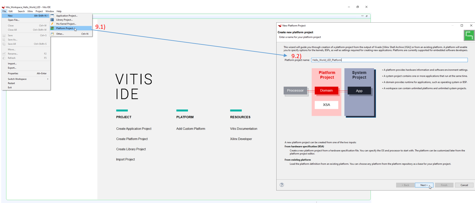
9.1) Create Platform Project from output of Vivado .XSA> File > New > Platform Project..
9.2) When New Platform Project pop up > Fill platform name then click Next >
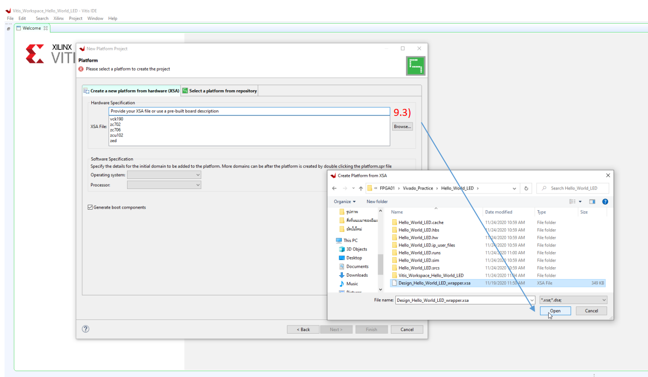
9.3) Click Browse… and find .XSA file then click Open
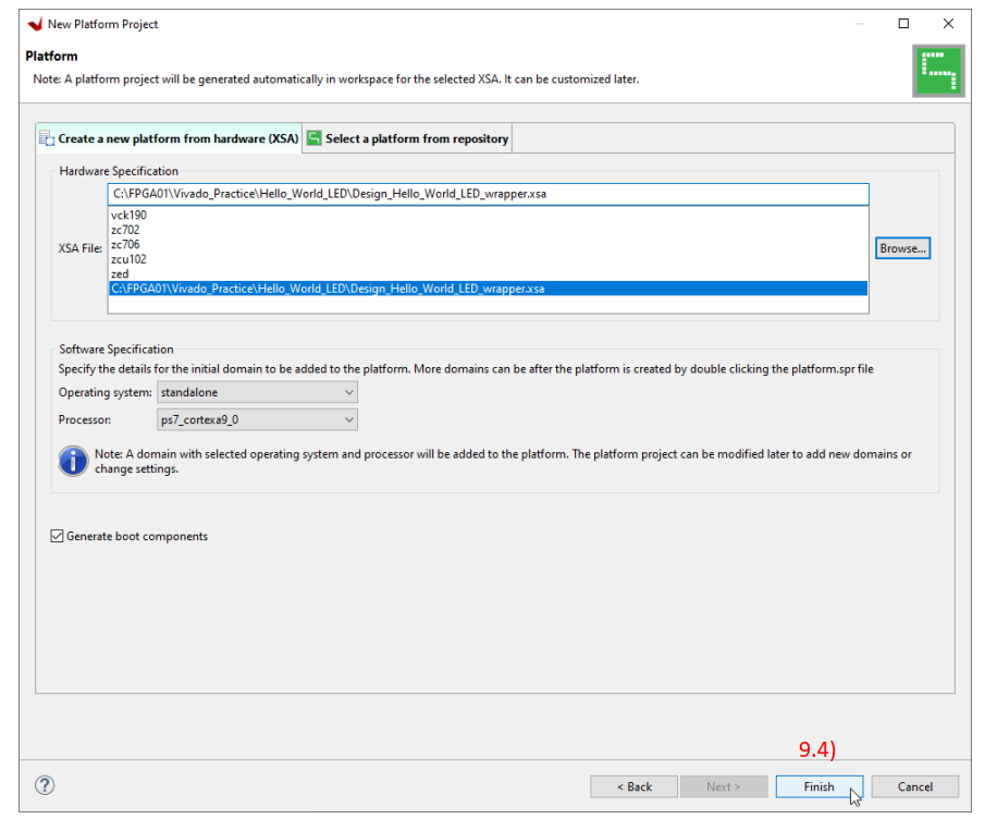
9.4) Click finish.
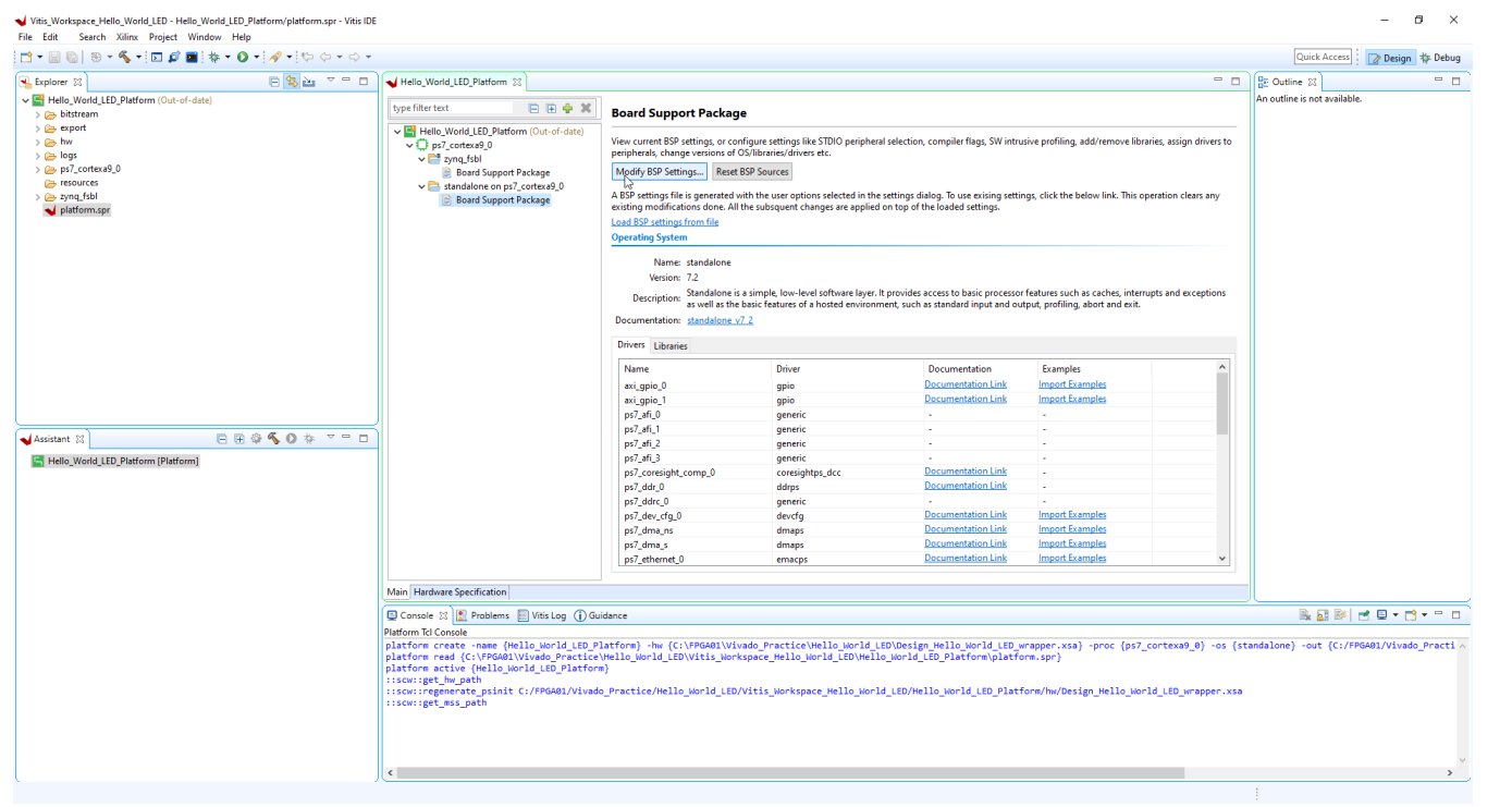
In this application we choose standalone operating system , we not running any kind of Linux and FreeRTOS here.
What we have here, Vitis IDE created board Support Package for us.
The BSP generate all firmware files that an application project will need to know how to interface to the different resources that were using in our hardware project.
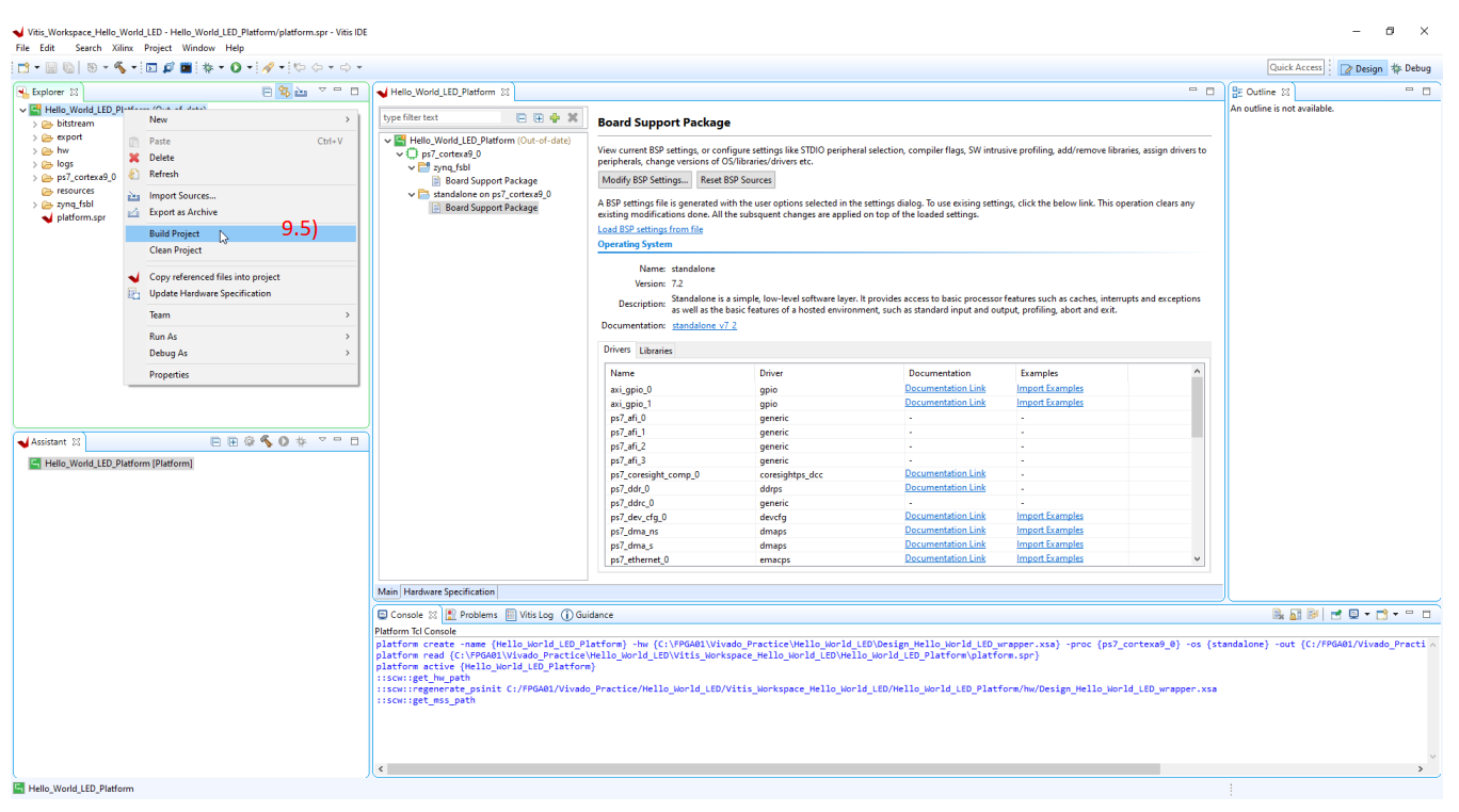
9.5) Next, we compile the project by right click on Hello_World_LED_Platform > Build Project
So in this step we just configuring hardware that we need something to run on its which is .C program that we going to create in the next step
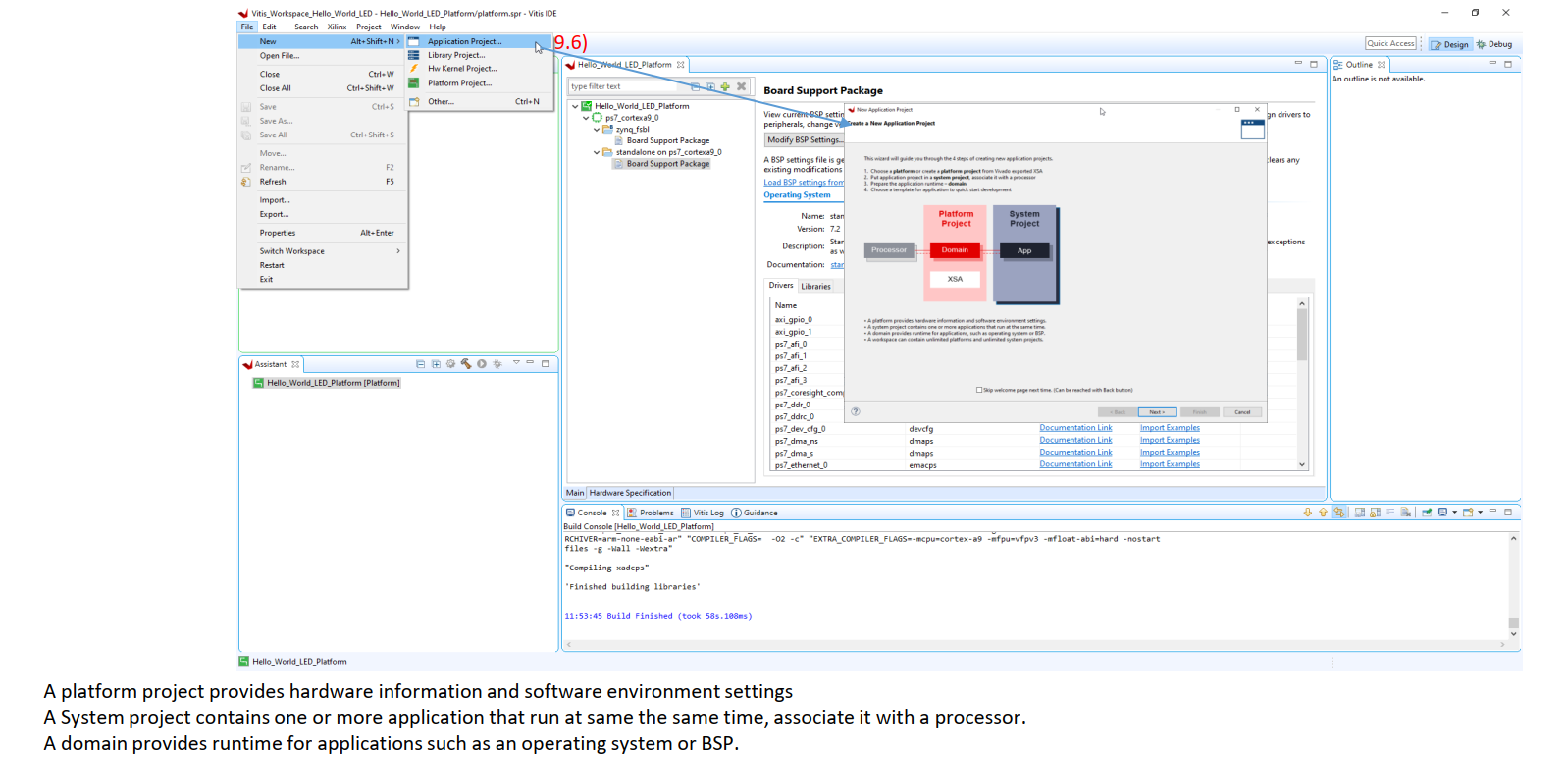
9.6) Create Application Project > File> New > Application Project..
New window will show up then click Next
This wizard will guide you through the 4 steps of creating new application projects.
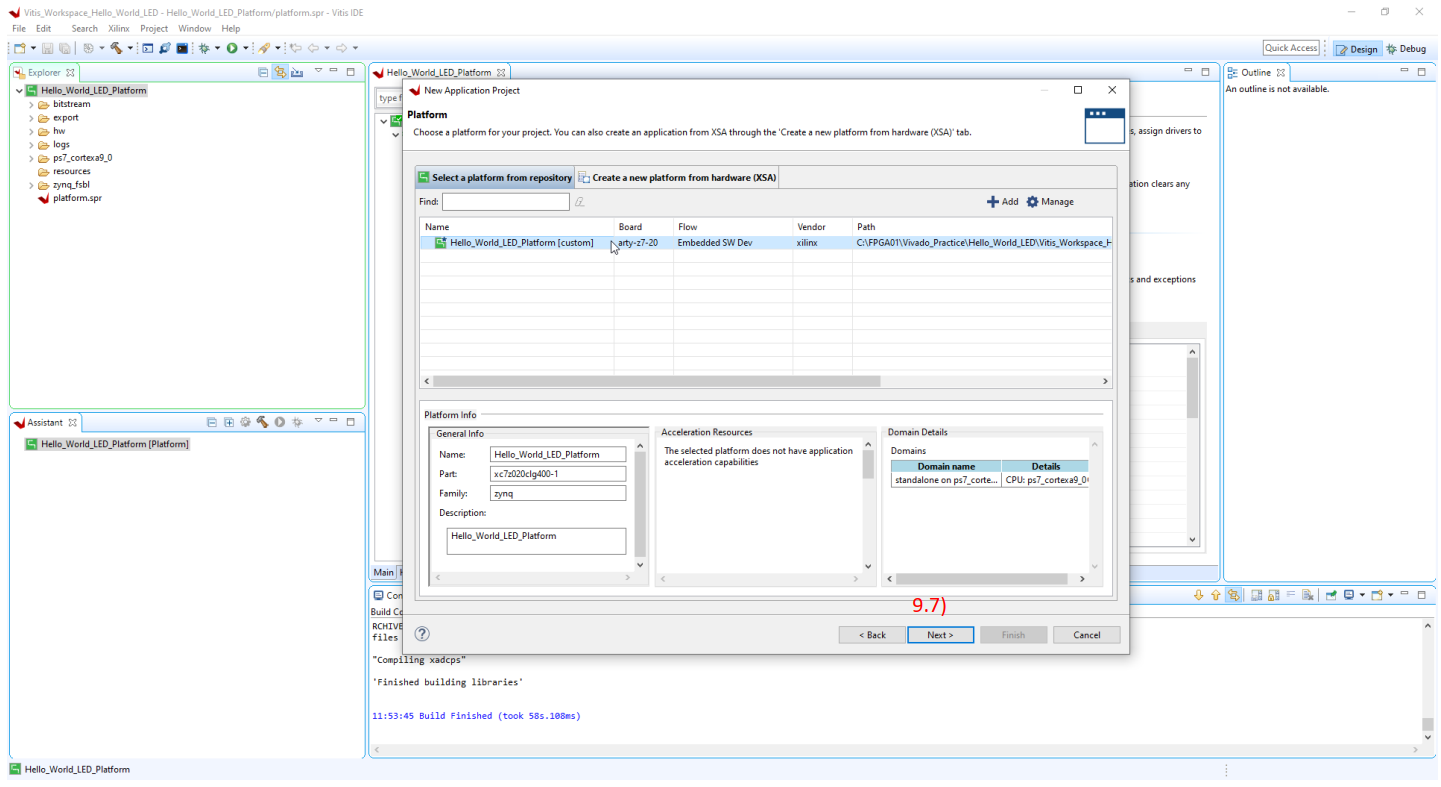
9.7) Select a platform that we would like to use then click Next.
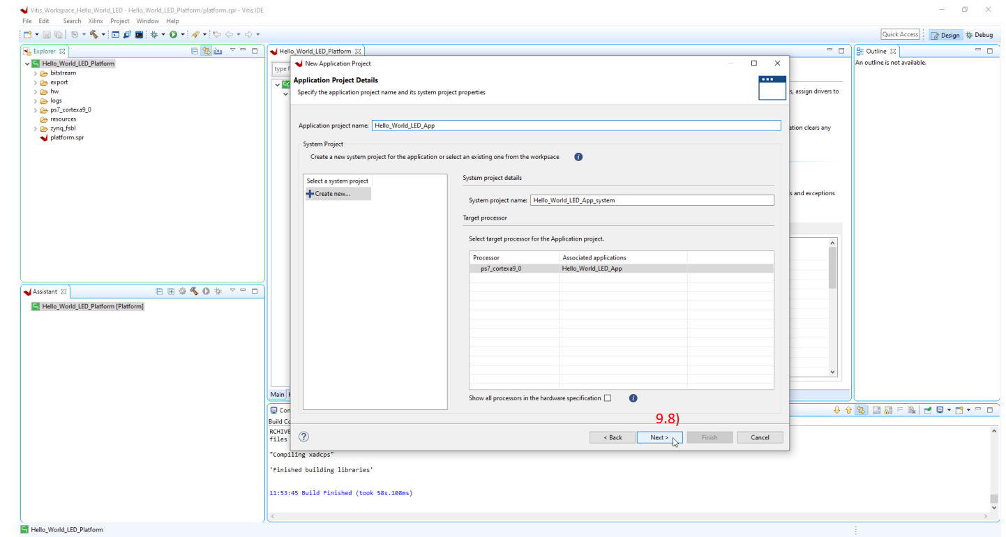
9.8) Fill application project name then click Next.
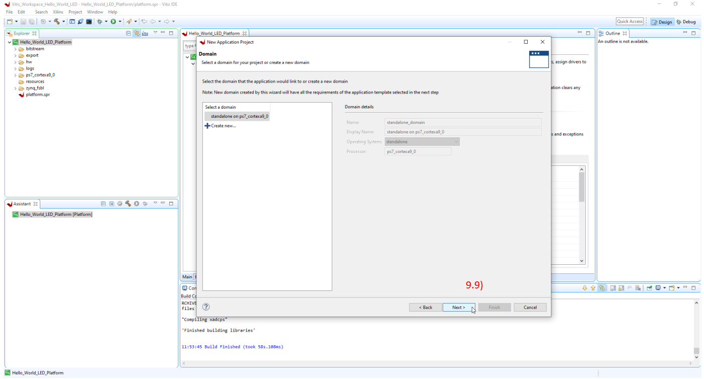
9.9) Check is it correct domain or not then click Next.
After that it going to pull some template.
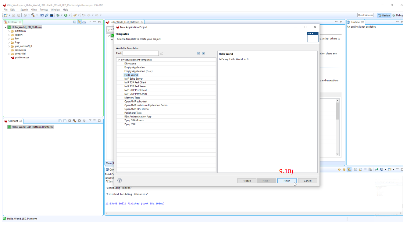
9.10) Select Hello World Template then click Next
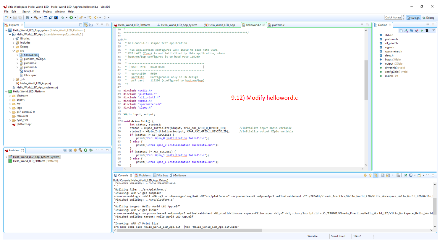
9.11) Let check the source code folder in Explorer left hand side to modify helloworld.c by double click on it.

9.12) Modify helloword.c as attached file.
Code example
/*
* helloworld.c: simple test application
*
* This application configures UART 16550 to baud rate 9600.
* PS7 UART (Zynq) is not initialized by this application, since
* bootrom/bsp configures it to baud rate 115200
*
* ------------------------------------------------
* | UART TYPE BAUD RATE |
* ------------------------------------------------
* uartns550 9600
* uartlite Configurable only in HW design
* ps7_uart 115200 (configured by bootrom/bsp)
*/
#include <stdio.h>
#include "platform.h"
#include "xil_printf.h"
#include <xgpio.h>
#include "xparameters.h"
#include "sleep.h"
XGpio input, output;
void driverInit() {
int status, status2;
status = XGpio_Initialize(&input, XPAR_AXI_GPIO_0_DEVICE_ID); //initialize input XGpio variable
status2 = XGpio_Initialize(&output, XPAR_AXI_GPIO_1_DEVICE_ID); //initialize output XGpio variable
if (status != XST_SUCCESS) {
print("Err: Gpio_0 initalization failed\n\r");
} else {
print("Info: Gpio_0 Initialization successful\n\r");
}
if (status2 != XST_SUCCESS) {
print("Err: Gpio_1 initalization failed\n\r");
} else {
print("Info: Gpio_1 Initialization successful\n\r");
}
}
void configGpio() {
XGpio_SetDataDirection(&input, 1, 0xF); //set first channel tristate buffer to input
XGpio_SetDataDirection(&input, 2, 0xF); //set second channel tristate buffer to input
XGpio_SetDataDirection(&output, 1, 0x0); //set first channel tristate buffer to output
/*
void XGpio_SetDataDirection (XGpio * InstancePtr,
unsigned Channel,
u32 DirectionMask
)
Set the input/output direction of all discrete signals for the specified GPIO channel.
Parameters:
InstancePtr is a pointer to an XGpio instance to be worked on.
Channel contains the channel of the GPIO (1 or 2) to operate on.
DirectionMask is a bitmask specifying which discrete are input and which are output. Bits set to 0 are output and bits set to 1 are input.
*/
}
int main()
{
init_platform();
driverInit();
configGpio();
int button_data = 0;
int switch_data = 0;
while(1){
button_data = XGpio_DiscreteRead(&input, 1); //get button data
switch_data = XGpio_DiscreteRead(&input, 2); //get switch data
XGpio_DiscreteWrite(&output, 1, button_data); //write switch data to the LEDs
//print message dependent on whether one or more buttons are pressed
if(button_data == 0b00000){
if(switch_data == 0b00){
xil_printf("switch&Button not selected\n\r");
}
else if (switch_data == 0b01)
xil_printf("switch_data 0 selected\n\r");
else if (switch_data == 0b10)
xil_printf("switch_data 1 selected\n\r");
else
xil_printf("error swith_data >2\n\r");
}
else if(button_data == 0b00001)
xil_printf("button 0 pressed\n\r");
else if(button_data == 0b00010)
xil_printf("button 1 pressed\n\r");
else if(button_data == 0b00100)
xil_printf("button 2 pressed\n\r");
else if(button_data == 0b01000)
xil_printf("button 3 pressed\n\r");
else
xil_printf("multiple buttons pressed\n\r");
usleep(200000); //delay
}
cleanup_platform();
return 0;
}
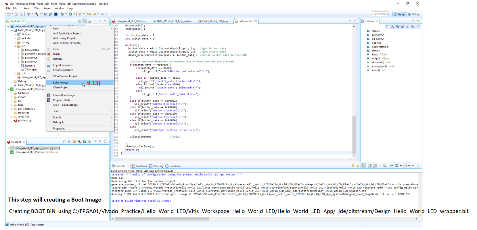
9.13) Right click on our application platform and then Click Build Project
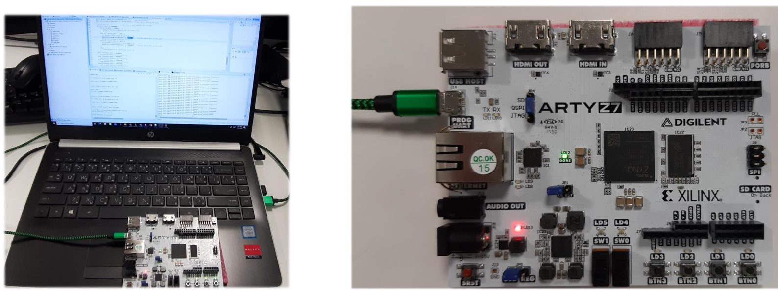
9.14) Connect Arty Z7-20 FPGA Development board and set JP4 to JTAG
Right-click on our application platform > Debug As > Launch Hardware
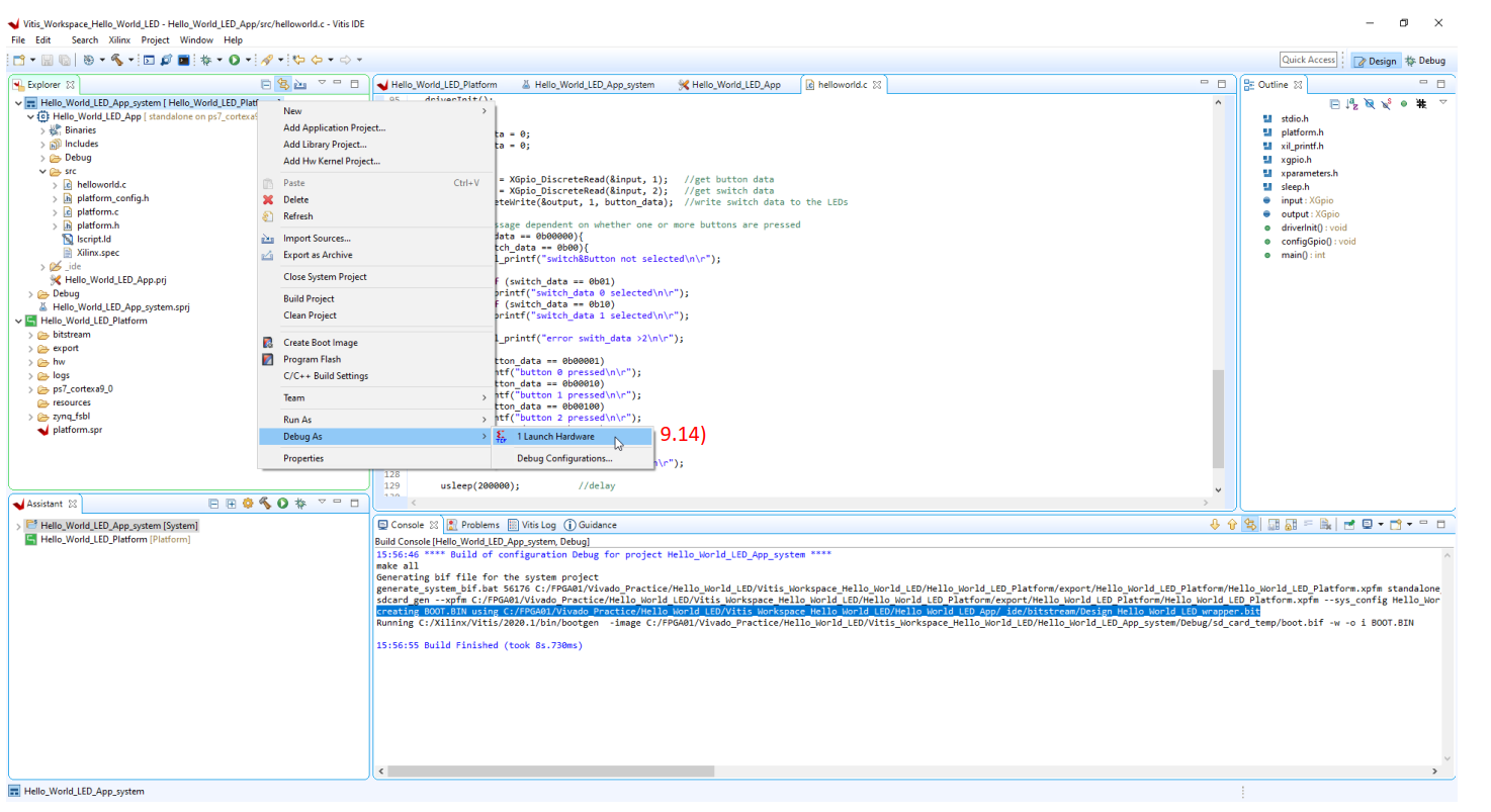
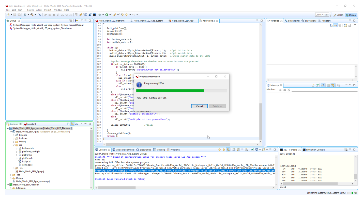
This step will programming FPGA…..
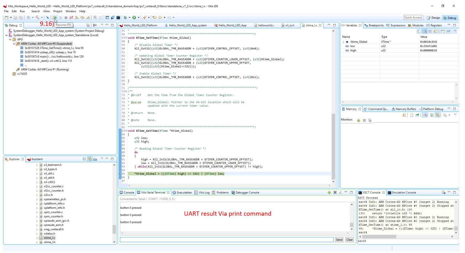
9.15) Select Vitis Serial Terminal and select serial port by click plus sign
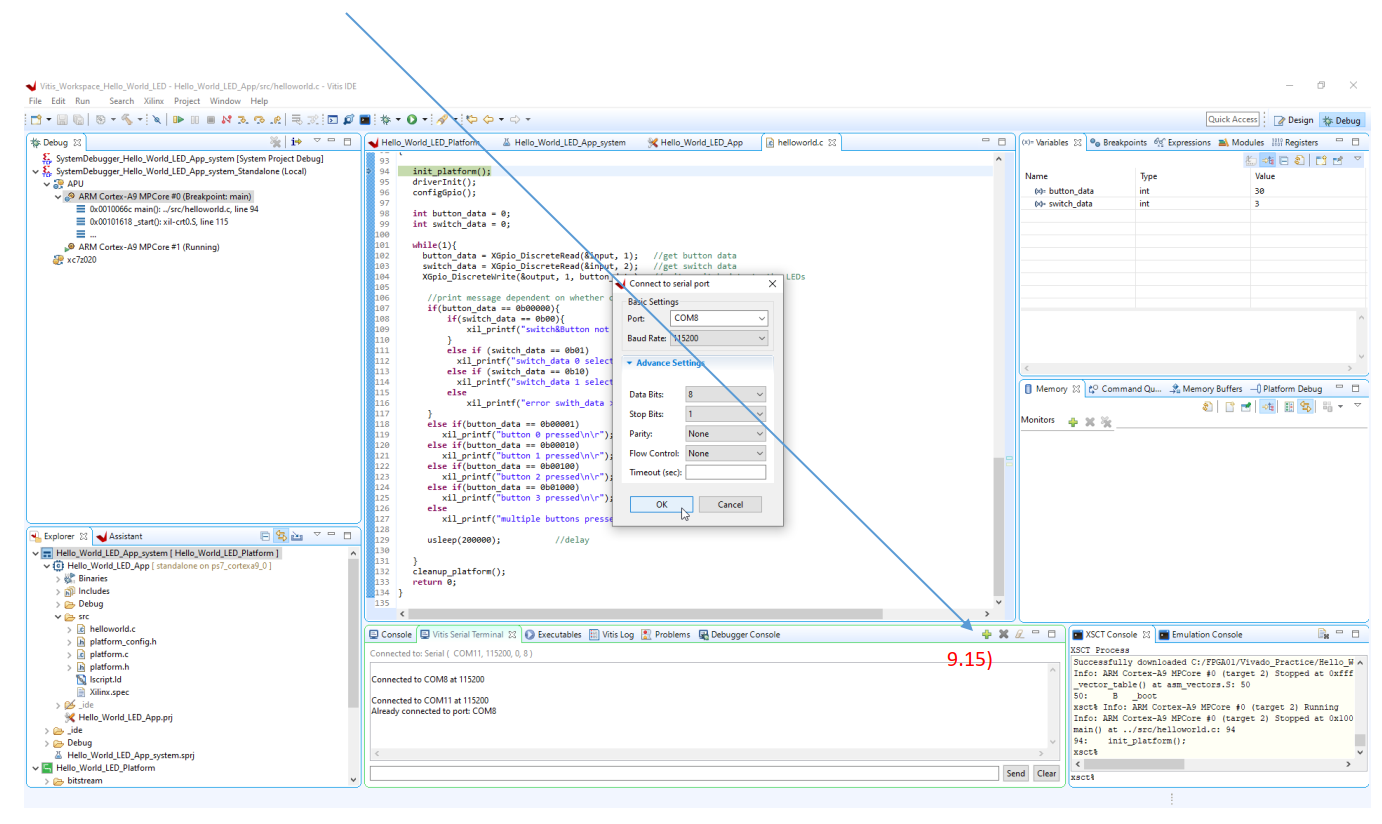
9.16) Click Play button, we will see result print on serial terminal and you can play around by press switch to see the result.
10. Program Boot image
Connect Arty Z7-20 FPGA Development board and set JP4 to JTAG
10.1) Right click on our application platform > Create Boot Image
10.2) Check I/O path for create Boot Image then click Create Image

10.3) Right click on our application platform > Program Flash
10.4) New window pop up then select proper boot.bin file then click Program
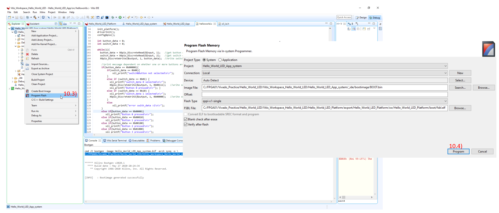
After Click Program, The boot image will be loaded to QSPI flash.

Change Jumper from JTAG to QSPI and re-connect USB cable.
Finally, Our program will be loaded from QSPI to program FPGA and we can test button/switch and LED as programmed.