Create an application for PS UART and UART Lite for communication testing on Xilinx Arty Z20
1. Open Vivado 2021.1 > Click File> Project >New
2. Create project name> PS UART and UART Lite

3. Project Type > Select RTL Project
4. Add constraints > Click next (we will add later)
5. Select Board > Arty Z7-20 then click next

6. Change target language to VHDL

7. Click > create block design

8. Change design name > Design_UART_Lite

9. Click add IP

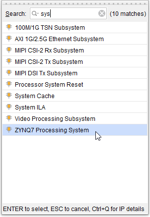
10. Search system > Select ZYNQ7 Processsing System

11. Click run Block automation then Click ok

12. Add UART IP >Search UART > add 2 UART lite

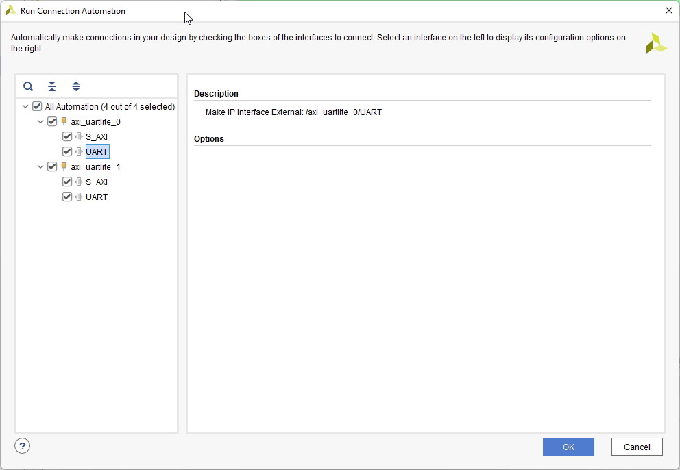
13. run Block automation then Click ok

14. Change the name for RX-Tx UART lite 0 and UART lite 1
14.1 right click rx signal select make external port

14.2 After changing name

15. Select PS UART 1 in Zynq block> double click at Zynq processing system block
15.1 Change UART 1 config to EMIO then click ok.

15.2 Make external ports for UART1_TX and UART1_RX

16. Add constraints file
16.1 Right click > create constraints file name PS_UART test.xdc

16.2 search and download Arty-Z7-20 then copy in to PS_UART test.xdc

17. Select output port for mapping
Check connector port -> https://digilent.com/reference/programmable-logic/arty-z7/reference-manual
And Check pin name from schematic for mapping -> https://digilent.com/reference/_media/reference/programmable-logic/arty-z7/arty_z7_sch.pdf
Use Arduino/chipKit Shield Connector for output port mapping
Select IO0 for rx_0
Select IO1 for tx_0
Select IO3 for rx_1
Select IO4 for tx_1
Select IO6 for UART1_RX_0
Select IO7 for UART1_TX_0

17.1 mapping signal in constraints file.

18. Create HDL wrapper >Right Click from design > let vivado manage wrapper and auto update

19. Run synthesis

20. Run implementation

21. Generate Bitstream

21.1 Bitstream genellation successfully then Click ok to see implementation

21.2 Check design timing and find any abnormal in design

22. Export hardware platform >platform type = fixed > Include bitstream

22. Launch vitis IDE for create application

23. Create application project

24. Select the platform

25. Create app UART lite

26.select templates

27. Modify hello world templates to app_uart_lite.c

Write copy the following code to app_uart_lite.c
/* modify from function from xuartps_polled_example.c and xuartlite_polled_example.c * using the local loopback mode. */ /***************************** Include Files *********************************/ #include#include "platform.h" #include "xparameters.h" #include "xuartps.h" #include "sleep.h" #include "xstatus.h" #include "xuartlite.h" #include "xil_printf.h" /************************** Constant Definitions *****************************/ /* * The following constants map to the XPAR parameters created in the * xparameters.h file. They are defined here such that a user can easily * change all the needed parameters in one place. */ #define PS_UART_1 XPAR_PS7_UART_1_DEVICE_ID #define UARTLITE_0 XPAR_UARTLITE_0_DEVICE_ID #define UARTLITE_1 XPAR_UARTLITE_1_DEVICE_ID /* * The following constant controls the length of the buffers to be sent * and received with the UartLite, this constant must be 16 bytes or less since * this is a single threaded non-interrupt driven example such that the * entire buffer will fit into the transmit and receive FIFOs of the UartLite. */ #define TEST_BUFFER_SIZE 16 /**************************** Type Definitions *******************************/ /***************** Macros (Inline Functions) Definitions *********************/ /************************** Function Prototypes ******************************/ int UartLitePolledExample(u16 DeviceId); int UartPsPolledExample(u16 DeviceId); /************************** Variable Definitions *****************************/ XUartLite UartLite; /* Instance of the UartLite Device */ XUartPs Uart_PS; /* Instance of the UART Device */ /* * The following buffers are used in this example to send and receive data * with the UartLite. */ u8 SendBuffer[TEST_BUFFER_SIZE]; /* Buffer for Transmitting Data */ u8 RecvBuffer[TEST_BUFFER_SIZE]; /* Buffer for Receiving Data */ /*****************************************************************************/ /** * * Main function to call the Uartlite polled example. * * @param None. * * @return XST_SUCCESS if successful, otherwise XST_FAILURE. * * @note None. * ******************************************************************************/ int main(void) { int Status; while(1) { /* * Run the UartLite polled example, specify the Device ID that is * generated in xparameters.h */ Status = UartLitePolledExample(UARTLITE_0); if (Status != XST_SUCCESS) { xil_printf("Uartlite polled Example Failed\r\n"); } xil_printf("Successfully ran Uartlite polled Example\r\n"); Status = UartLitePolledExample(UARTLITE_1); if (Status != XST_SUCCESS) { xil_printf("Uartlite polled Example Failed\r\n"); } xil_printf("Successfully ran Uartlite polled Example\r\n"); /* * Run the Uart_PS polled example , specify the the Device ID that is * generated in xparameters.h */ Status = UartPsPolledExample(PS_UART_1); if (Status != XST_SUCCESS) { xil_printf("UART Polled Mode Example Test Failed\r\n"); } xil_printf("Successfully ran UART Polled Mode Example Test\r\n"); usleep(2000000);//delay } } /****************************************************************************/ /** * This function does a minimal test on the UartLite device and driver as a * design example. The purpose of this function is to illustrate * how to use the XUartLite component. * * This function sends data and expects to receive the data through the UartLite * such that a physical loopback must be done with the transmit and receive * signals of the UartLite. * * This function polls the UartLite and does not require the use of interrupts. * * @param DeviceId is the Device ID of the UartLite and is the * XPAR_ _DEVICE_ID value from xparameters.h. * * @return XST_SUCCESS if successful, XST_FAILURE if unsuccessful. * * * @note * * This function calls the UartLite driver functions in a blocking mode such that * if the transmit data does not loopback to the receive, this function may * not return. * ****************************************************************************/ int UartLitePolledExample(u16 DeviceId) { int Status; unsigned int SentCount; unsigned int ReceivedCount = 0; int Index; /* * Initialize the UartLite driver so that it is ready to use. */ Status = XUartLite_Initialize(&UartLite, DeviceId); if (Status != XST_SUCCESS) { return XST_FAILURE; } /* * Perform a self-test to ensure that the hardware was built correctly. */ Status = XUartLite_SelfTest(&UartLite); if (Status != XST_SUCCESS) { return XST_FAILURE; } /* * Initialize the send buffer bytes with a pattern to send and the * the receive buffer bytes to zero. */ for (Index = 0; Index < TEST_BUFFER_SIZE; Index++) { SendBuffer[Index] = '0'+ Index; RecvBuffer[Index] = 0; } xil_printf("\n Print SendBuffer : %s \n",SendBuffer); xil_printf("\n Print RecvBuffer : %s \n",RecvBuffer); xil_printf("\n This is XPAR_UARTLITE : %d \n",DeviceId); /* * Send the buffer through the UartLite waiting til the data can be sent * (block), if the specified number of bytes was not sent successfully, * then an error occurred. */ SentCount = XUartLite_Send(&UartLite, SendBuffer, TEST_BUFFER_SIZE); if (SentCount != TEST_BUFFER_SIZE) { return XST_FAILURE; } /* * Receive the number of bytes which is transferred. * Data may be received in fifo with some delay hence we continuously * check the receive fifo for valid data and update the receive buffer * accordingly. */ ReceivedCount = 0; while (ReceivedCount < TEST_BUFFER_SIZE) { ReceivedCount += XUartLite_Recv(&UartLite, RecvBuffer + ReceivedCount, TEST_BUFFER_SIZE - ReceivedCount); } /* * Check the receive buffer data against the send buffer and verify the * data was correctly received. */ for (Index = 0; Index < TEST_BUFFER_SIZE; Index++) { xil_printf("\n Print RecvBuffer UARTLITE: %c \n",RecvBuffer[Index] ); if (SendBuffer[Index] != RecvBuffer[Index]) { return XST_FAILURE; } } return XST_SUCCESS; } int UartPsPolledExample(u16 DeviceId) { int Status; XUartPs_Config *Config; unsigned int SentCount; unsigned int ReceivedCount; u16 Index; u32 LoopCount = 0; /* * Initialize the UART driver so that it's ready to use. * Look up the configuration in the config table, then initialize it. */ Config = XUartPs_LookupConfig(DeviceId); if (NULL == Config) { return XST_FAILURE; } Status = XUartPs_CfgInitialize(&Uart_PS, Config, Config->BaseAddress); if (Status != XST_SUCCESS) { return XST_FAILURE; } /* Check hardware build. */ Status = XUartPs_SelfTest(&Uart_PS); if (Status != XST_SUCCESS) { return XST_FAILURE; } /* Use local loopback mode. */ XUartPs_SetOperMode(&Uart_PS, XUARTPS_OPER_MODE_LOCAL_LOOP); /* * Initialize the send buffer bytes with a pattern and zero out * the receive buffer. */ for (Index = 0; Index < TEST_BUFFER_SIZE; Index++) { SendBuffer[Index] = '0' + Index; RecvBuffer[Index] = 0; } xil_printf("\n Print SendBuffer : %s \n",SendBuffer); xil_printf("\n Print RecvBuffer : %s \n",RecvBuffer); xil_printf("\n This is UART : %d \n",DeviceId); /* Block sending the buffer. */ SentCount = XUartPs_Send(&Uart_PS, SendBuffer, TEST_BUFFER_SIZE); if (SentCount != TEST_BUFFER_SIZE) { return XST_FAILURE; } /* * Wait while the UART is sending the data so that we are guaranteed * to get the data the 1st time we call receive, otherwise this function * may enter receive before the data has arrived */ while (XUartPs_IsSending(&Uart_PS)) { LoopCount++; } /* Block receiving the buffer. */ ReceivedCount = 0; while (ReceivedCount < TEST_BUFFER_SIZE) { ReceivedCount += XUartPs_Recv(&Uart_PS, &RecvBuffer[ReceivedCount], (TEST_BUFFER_SIZE - ReceivedCount)); } /* * Check the receive buffer against the send buffer and verify the * data was correctly received */ for (Index = 0; Index < TEST_BUFFER_SIZE; Index++) { xil_printf("\n Print RecvBuffer UART: %c \n",RecvBuffer[Index] ); if (SendBuffer[Index] != RecvBuffer[Index]) { return XST_FAILURE; } } /* Restore to normal mode. */ XUartPs_SetOperMode(&Uart_PS, XUARTPS_OPER_MODE_NORMAL); return XST_SUCCESS; }
28. Right-click to build the project

29. Connect a wire to pair UART communication
> IO0 (UARTLite 0 Rx) to IO1 (UARTLite 1Tx),
> IO3 (UARTLite 1 Rx) to IO4 (UARTLite 1 Tx),
> IO6 (UART1_Rx_0) to IO7 (UART1_Tx_0),

30. Right-click app_uartlite then select debug as >launch on hardware

31. Click play to see result in Vitis Serial Terminal

32. Here result of UARTLITE 0

32. Here result of UARTLITE 1

33. Here result of UART PS 1

How to create boot image
1. Right-click app_uartlite then select Create Boot image

2. use default file path then click Create Image


